![Frisbee Thrower [ My Disc in a Box ]](https://blogger.googleusercontent.com/img/b/R29vZ2xl/AVvXsEgzCyFURQySzD5aei5-m5H16rH2qIeDDjPtMxoMMiX-dbxdLYX-A3H_YPz_DzLxgEo0ZgMlQ-O_t9EwvURNzY4oDRsF1IVJG4CEzmH9L0I5EQRgfnT0u0KX4fr5TOJ92CntlxtA9MQ5Pqzv/s770/2013-02-13_120544.png)
Brainstorming
 |
| pugh chart |
System & Sub-systems
 |
| overview |
The primary function of our design is to accurately throw Frisbee-type discs at targets. These discs are 6" in diameter and made of a relatively lightweight, flexible plastic. Additional requirements include the ability to fire on targets in a 4' wide x 3' high area at a distance of 10'. The targets will be of varying sizes 1.5x, 2x, and 3x the disc diameter and will be marked with colored retro-reflective tape. Our machine must fit within a 2'x2'x2' cube and be able to receive a manually loaded stack of at least three Frisbees. Finally, the loading must be done in less than 15 seconds; the machine must be able to fire 3 Frisbees in 20 seconds and must have 80% accuracy firing at the 3x targets and about 50% on the 2x targets. Additional features to the design are encouraged and will be considered as coolness factors.
Given these constraints and requirements our team has developed a preliminary design with a variety of actuation and sensing capabilities to enable it to achieve these goals.
Sensing
 |
| CMUcam |
The CMU cam can be seen in figure above as the green component attached to the hopper/loading subsystem. We will be using this device given its relative ease of use in interfacing with the Arduino microcontroller in addition to the fact that this device can be acquired by our team for free and budget concerns are very important for this project. There is currently a design debate occurring within our team in relation to the placement of the camera, whether to have it attached to the launching mechanism so that the camera moves and rotates with the system, or to mount the camera to the frame of the system where it will not be able to move. The basic debate is over the complexity of the coding and communication between the Arduino and CMU cam.
Another sensing design decision that needs to be determined is how the machine will know that a Frisbee has loaded, been launched, and ready to be reloaded. There has been some debate to whether or not we need sensing or can simply time the motors to spin at a set rpm which will allow the discs to constantly launch without any sensing being necessary.
Loading
 |
| hopper & pusher |
Our hopper/loading mechanism will utilize a timing belt type of conveyor that will bring the disc towards the launching subsystem. We will have an additional point of actuation within the hopper that allows just one disc to drop down to the belt at a time which is why the hopper appears to be sitting at a 30° angle with respect to the conveyor belt.
Additionally, our team decided that the "coolness" factor we wanted to tackle, assuming that we will have the time, is to develop a catching subsystem that can be added onto the hopper/loading mechanism. We would be designing the catching subsystem under the assumption that it would only be catching Frisbees from devices built by other groups based on the design constraints presented in the project description. Under this assumption we can develop a hole the same size as the targets we will be shooting at and use retro-reflective tape around it to allow the other devices to see the target/catching mechanism.
Elevating & Rotating
 |
| aiming mechanism |
The elevating subsystem will play in integral part in our devices capability to address the accuracy constraints given in the project description. The initial angle in projectile equations is a key piece of information that will play a major role in our targeting system. For our design we have opted to use a ball screw mechanism that is powered by a servo motor. We selected this mechanism due to the fact that angle will be able to be adjusted very slowly and will allow for precision of 0.1°.
Lastly we have the rotating subsystem outlined. The current CAD model depicts a thrust ball bearing that is geared by a servo and allows the entire system to rotate so that the x-axis component of the targeting system can be realized. Currently we are still debating the exact mechanism to use for this subsystem as there is debate of simple coupling the servo directly to the shaft that will rotate the launcher.
Launching
 |
| flywheel & track |
The launching subsystem is of relatively simple design. We will have a spinning wheel in the middle powered by a large motor spinning at a to-be-determined rpm. The width of the channel will be 6" so that the Frisbee fits snugly and will not vibrate or jostle around leading to inaccuracies. A design decision that still needs to be solidified is the placement of the motor powering the wheel. In the figure it is shown as attached on top of the wheel, however, pending the final dimensions of the design the motor may be placed underneath the wheel. By having the motor under the wheel the design would be more aesthetically pleasing overall and also reduce the necessary length of the wiring which is always ideal.
Functional architecture
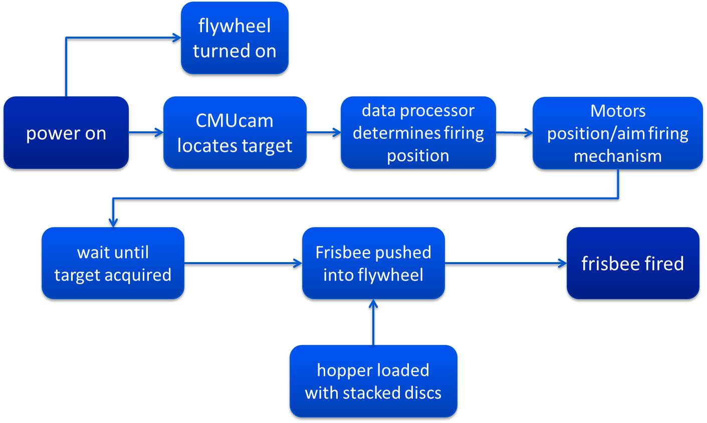 |
| functional block diagram |
Physical architecture
 |
| physical block diagram |